PCB Design Guide
Layout guide
Using a multilayer board provides an easy-to-use layout of Neutis interfaces and power lanes. Pay attention to the following recommendations when making a custom PCB for Neutis:
-
Use one of PCB layers as GND plane and connect all GND pins of Neutis connector to this layer with vias.
-
Place DC/DC for power Neutis as close as possible to a connector. If you use high standoffs and connectors (> 3,00 mm) you can place DC/DC under Neutis in the same layer with Neutis connectors.
-
Match length of high-speed signal lanes. SDIO, CSI, HDMI, EPHY lines are matched with 0.05 mm tolerance in Neutis.
-
Pay attention to antenna placement in Neutis.
-
Pin35(PL9) has to be used as a USB power enable for USB-OTG, Neutis raises this pin after the USB-OTG mode initialization by Linux. Pin33(PL8) is used as a USB ID pin configured by Linux, it must be externally tied to 3V3_IN.
Linux configuration example (Device Tree fragment):
reg_usb0_vbus: usb0-vbus {
compatible = "regulator-fixed";
regulator-name = "usb0-vbus";
regulator-min-microvolt = <5000000>;
regulator-max-microvolt = <5000000>;
enable-active-high;
gpio = <&r_pio 0 9 GPIO_ACTIVE_HIGH>; /* PL9 */
status = "okay";
};
usbphy {
usb0_id_det-gpios = <&r_pio 0 8 GPIO_ACTIVE_HIGH>; /* PL8 */
usb0_vbus-supply = <®_usb0_vbus>;
status = "okay";
};For more detailed information please proceed Neutis BSP. Theoretically, you can choose other GPIO pins for these purposes.
-
Pin43(1V2_SYS_ENABLE) is an enable pin for the internal DC/DC for 1V2 system power, it must be left floating. 1V2_SYS_ENABLE is equipped with an internal pull-up to 3V3_IN. If controlled externally, must be held high for valid module operation.
-
All reserved or other unused pins have to be left floating.
You will find more details inside Neutis developer board schematics.
Placement of connectors and standoffs shown in the picture below. Use this footprint in your project with Neutis. Check connectors and standoffs documentation before laying out (https://www.hirose.com , https://www.we-online.com).
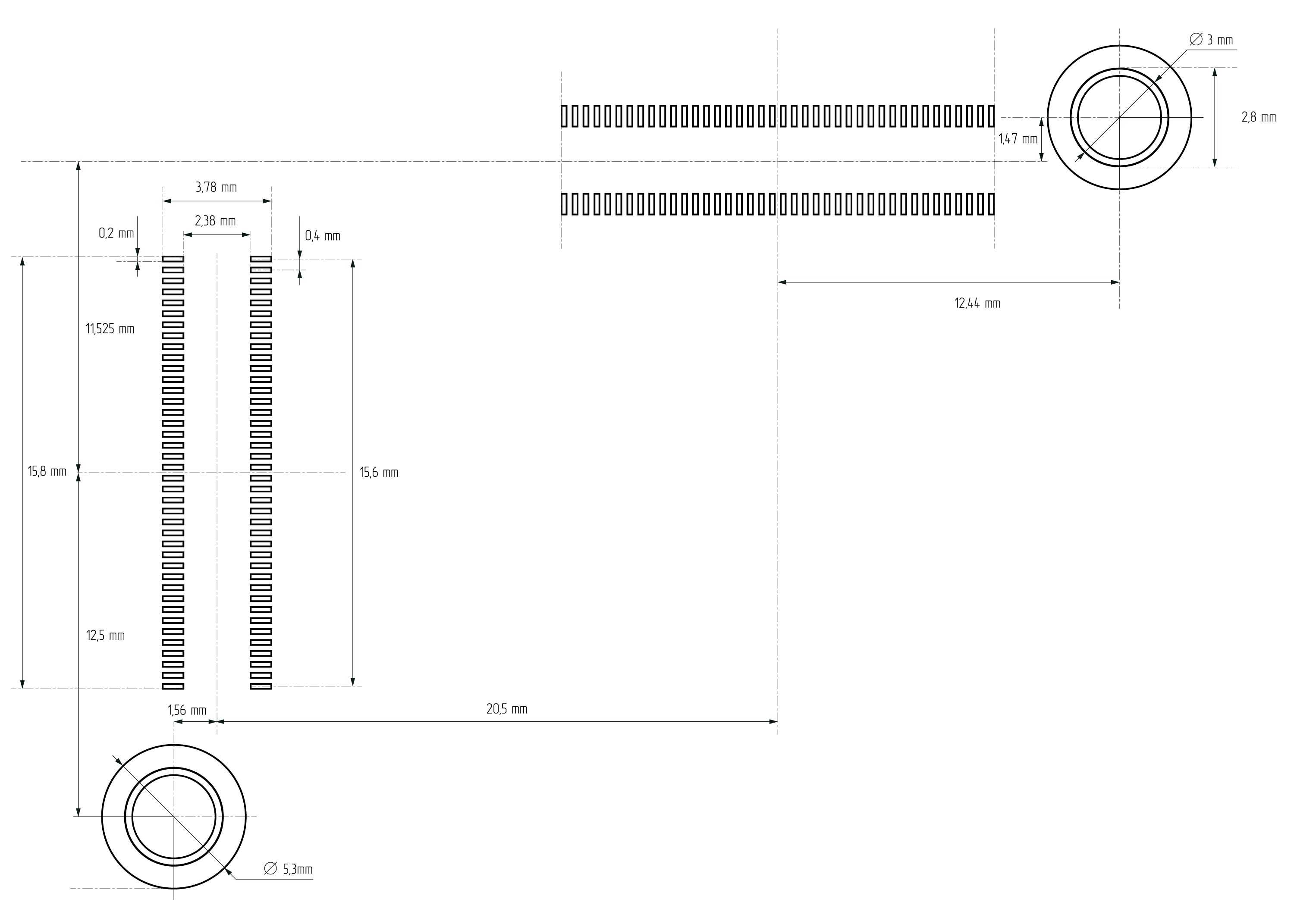
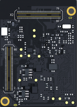
Connector
There are two DF40C-80DP-0.4V(51) connectors on Neutis. You need two “receptacle” connectors and two standoffs with thread M2 to connect Neutis.
| Height | Connectors part number | Mouser | Digi-key |
|---|---|---|---|
| 1,5mm | DF40C-80DS-0.4V(51) | 798-DF40C80DS0.4V51 | H11633CT-ND |
| 2,0mm | DF40C(2.0)-80DS-0.4V(51) | 798-DF40C2080DS04V51 | H11773CT-ND |
| 3,0mm | DF40HC(3.0)-80DS-0.4V(51) | 798-DF40HC3080D04V51 | DF40HC(3.0)-80DS-0.4V(51)-ND |
| 3,5mm | DF40HC(3.5)-80DS-0.4V(51) | 798-DF40HC3580DS4V51 | H11997CT-ND |
| 4,0mm | DF40HC(4.0)-80DS-0.4V(51) | 798-DF4HC4080DS04V51 | H11919CT-ND |
| Height | Standoff part number | Mouser | Digi-key |
|---|---|---|---|
| 1,5mm | 9774015243R | 710-9774015243R | 732-7069-1-ND |
| 2,0mm | 9774020243R | 710-9774020243R | 732-7073-1-ND |
| 3,0mm | 9774030243R | 710-9774035243R | 732-7088-1-ND |
| 3,5mm | 9774035243R | 710-9774030243R | 732-7085-1-ND |
| 4,0mm | 9774040243R | 710-9774040243R | 732-7090-1-ND |